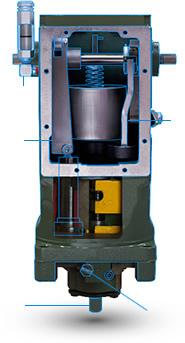
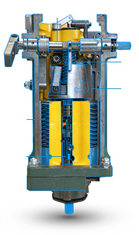
So how exactly does a governor work? The 'black box' still holds many mysteries for some. Here it is in a nutshell based on the well-known UG8 model.
1. Needle Valve
The needle valve controls the flow of oil between the compensation piston and the oil sump.
2. Large Dashpot Compensation Link
The compensation piston is used as temporary feedback to the pilot valve, which stabilises the system during the speed transient.
3. Pump
Provides oil pressure for the governor.
4. Accumulators
The function of the accumulator pistons and springs are to provide and store oil pressure for operation.
5. Power piston and link
The purpose of the power piston and link is to rotate the governor output shaft to either increase or decrease fuel position.
6. Ballhead assembly
The purpose of the ballhead is to sense changes in actual speed as compared to the speed setpoint applied by the speeder spring.
7. Speeder spring
The purpose of the speeder spring is to change the speed setpoint.
8. Output shaft / terminal shaft
The ouput shaft provides output connection from the governor to the fuel control of the prime mover.
9. Oil level sight glass
Facilitates the maintenance of oil quality and quantity.
10. Driveshaft
The drive shaft is rotated by the prime mover.